

0538-5089056


0538-5089056
Second-class standard platinum resistance thermometers are calibrated by first-class platinum resistance thermometer standard devices using the fixed-point method. The so-called fixed-point method, that is, the thermometer to be examined were placed in the water three-phase point, tin solidification point and zinc solidification point, measuring its resistance value, and then the results of the test and the last cycle of the test results, and then determine whether its stability meets the requirements.
1. The composition of the first-class platinum resistance thermometer standard device
① Standard device: a group of first-class standard platinum resistance thermometer, three, model WZPB-1.
② Calibration equipment: DC comparison ritual temperature bridge, the basic error 1 × 10⁻⁶R + 10 △ R (1Ω ≤ R ≤ 1000Ω), model QJ58; water three-phase point bottle and its insulation device; tin point furnace and its temperature control device, metal purity (by weight) of 99.999%; zinc point furnace and its temperature control device, metal purity (by weight) of 99.999%; platinum resistance furnace and its temperature control device. Temperature control device, in the placement of the temperature sensing element in the 100mm range of the axial maximum temperature difference does not exceed 1K.
2. Generation of three fixed points
2.1 Generation of water three-phase point
2.1.1 Water three-phase point
Water three-phase point temperature is a pressure of 610.615Pa in a sealed container, ice, water and saturated steam between the three-phase equilibrium temperature, which defines the value of +0.01 ℃ (273.16K), water, a phase equilibrium diagram shown in Figure 1. three-phase point of the water is not subject to the influence of atmospheric pressure, it is made out of the temperature can be maintained in a few months in the 0.1mK within the same.
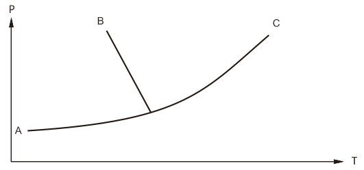
Fig.1 An equilibrium diagram of water
2.1.2 Generation and preservation of water three-phase points
①Pre-cooling: before freezing, put the bottle of three-phase point in the thermos flask with crushed ice and water to pre-cool overnight, so that its temperature drops to about 1℃.
②Freezing: use cotton dipped in alcohol to scrub the thermometer insertion well of the three-phase point bottle clean, and no water should be left in the well. Repeatedly with cotton dipped in liquid nitrogen in the plug well to pull, so that the plug well around the formation of ice sets. At the beginning of the cotton less, pull the amplitude is small, try to make the bottom of the plug well around the first ice. To be thick enough ice (about 8mm), more cotton, pulling amplitude can be larger, so that the ice layer gradually lengthened, thickened. Ice thickness of 10mm can be. Freezing process should pay special attention to prevent the water three-phase point bottle liquid surface icing. Once the ice can be covered by hand, so that the ice melting.
③ Preservation: The water triple-phase point bottle is placed in a thermos bottle containing ice and water for preservation, the water at the bottom of the bottle is drained every day, crushed ice is added, and the mouth of the bottle is covered with an insulating material.
Water three-phase point bottle frozen after the first few hours, due to the growth of ice crystals or strain within the measured water three-phase point temperature rises faster, about a day and night after stabilization before use.
2.2 Generation of Tin Freezing Point
2.2.1 Metal cooling curve and thermopanel
In order to achieve the solidification point of the metal, the metal is generally first fully melted and then cooled down cooling curve (i.e., temperature and time relationship curve) is shown in Figure 2. which ABD part of the uniform liquid phase cooling process; horizontal part of the EC is the equilibrium phase transition process, at this time the temperature of the material is unchanged, the temperature on the line of the EC is the solidification temperature of the material; EC this period of time is the temperature of the time of the panel: BDE part of the equilibrium phase transition is said to have a supercooling phenomenon before BDE part that in the equilibrium phase transition before the phenomenon of subcooling, once the beginning of a large number of crystallization, the system temperature that is to return to the normal solidification point, the thermopanel appeared; CF part of the crystallization is completed, is a solid-phase cooling process.
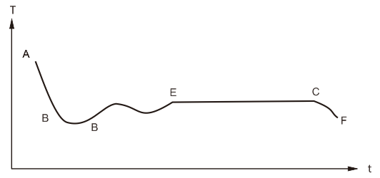
Fig. 2 Metal cooling curve
2.2.2 Generation of the solidification point of tin
High purity tin solidifies with a large degree of subcooling (up to 20-30°C). In order to obtain a good temperature ping, must use a slow solidification called "external crystallization nucleation" of the induction technology, the specific operation process is as follows:
① Preparation: the tin point furnace and control cabinet connected to confirm the correct wiring; connected to the gas pipe and install a flow meter on top of it; will monitor the thermocouple into the tin point furnace thermometer inserted in the well, the thermocouple connected to the digital multimeter.
② Temperature control: thermostat given the value of 1.005mV, 60-segment programmable temperature controller curve in Figure 3, the actual value of the thermostat is 1.005mV plus a certain moment of the program given the value of the instrument. Figure 4 for the tin point furnace heating curve.
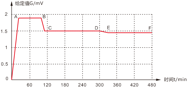
Fig.3 Programmable Temperature Controller Curve for Tin Point Furnace
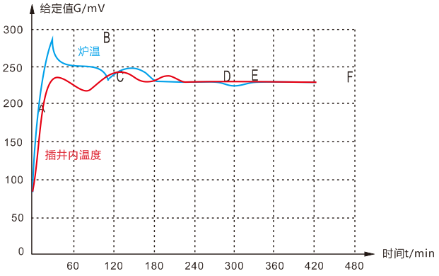
Fig.4 Tin spot furnace heating curve
First 60-segment programmable temperature controller to go to the AB section in Figure 3, so that the tin is completely melted, the maximum temperature at the time of melting is about 20K higher than the solidification point of tin. Then 60 programmable temperature controllers go to Figure 3 in the BCD section, the furnace temperature control than the solidification point of tin 2-3K, maintained for 10min, during which the temperature change should not exceed 0.2K. Then 60 programmable temperature controllers go to Figure 3 in the DE section, so that the molten tin at a rate of 0.15K/min temperature reduction. When monitoring the value of the thermocouple down to the tin solidification point near (high 0.1K or so), start blowing nitrogen, nitrogen volume flow rate of about 15L/min. closely observe the value of the thermocouple, when it suddenly stops dropping and quickly back up, immediately stop blowing (blowing time of about 10min), observing the value of the thermocouple, to be back up to the temperature of the solidification point of tin near the thermocouple, remove the thermocouple, and then special stainless steel inducer bar Insert the special stainless steel inducing rod into the well, induced 1min after removal. At this time, the tin solidification point temperature ping appeared, the temperature is 231.928 ℃. Furnace temperature control than the solidification point of low 2K or so. Warm ping time of about 2h.
2.3 Generation of zinc solidification point
① Preparation: the zinc point furnace and control cabinet connected to confirm that the wiring is correct; will monitor the thermocouple into the zinc point furnace thermometer insert wells, thermocouple connected to a digital multimeter.
② Temperature control: thermostat given the value of 2.00mV, 60-segment programmable temperature controller curve in Figure 5, the actual value of the thermostat is 2.00mV plus a certain moment of the program given the value of the instrument.
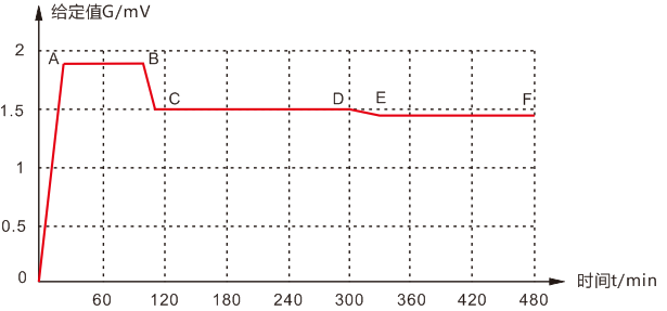
Fig.5 Programmable temperature controller curve for zinc point furnace
First 60-segment programmable temperature controller to go to the AB section in Figure 5, so that the zinc is completely melted, the maximum temperature at the time of melting than the zinc solidification point of about 20K higher. Then 60 programmable temperature controllers go to Figure 5 in the BCD section, the furnace temperature control than the zinc solidification point of 2 ~ 3K, maintained for 10min, during which the temperature change should not exceed 0.2K. Then 60 programmable temperature controllers go to Figure 5 in the DE section, so that the molten zinc at a rate of 0.15K/min temperature reduction. When the monitoring thermocouple value stops falling and begins to rise, remove the thermocouple, the quartz tube induced rod inserted into the plug well, induced 1min and then removed. At this time the zinc solidification point temperature ping appeared. The temperature is 419.527℃, and the furnace temperature is controlled at about 2K lower than the solidification point. The thermopanel time was about 3.5h.
3. The second class standard platinum resistance thermometer checking
3.1 Test principle
Determination principle block diagram in Figure 6.
3.2 A second standard platinum resistance thermometer calibration steps
① water three-phase point generation: 24h before the test water three-phase point generation and save.
② Annealing: temperature sensing element for the quartz cross skeleton of the thermometer, the verification should be in the upper limit of the temperature 630 ℃ annealing 2h.
③ Measurement WSn: According to 2.2.2 to establish the tin solidification point temperature ping, measuring the inspected second-class standard platinum resistance thermometer RSn (platinum resistance thermometer into the tin point furnace, should be placed in the annealing furnace before preheating). Measurement of RSn and then put the thermometer indoors to cool down, measure the thermometer Rtp (measurement before the three-phase point of the bottle inside the melt, that is, in the three-phase point of the bottle insert well filled with water slightly higher than 0 ℃, rotate the bottle, so that the ice jacket rotation), the measurement results will be filled into the record table.
④ Measurement of WZn: Establish the zinc solidification point temperature ping according to 2.3, and measure the RZn of the inspected second-class standard platinum resistance thermometer (the platinum resistance thermometer should be placed in the annealing furnace to preheat before it is put into the zinc point furnace). Measure RZn and then put the thermometer in the room to cool down, and then measure the Rtp of the thermometer. fill in the measurement results in the record table.
⑤ Organize the test results: fill in the "second-class standard platinum resistance thermometer comprehensive results of the table", out of the certificate of verification, verification cycle of 2 years.
3.3 Precautions for calibration of a second standard platinum resistance thermometer
3.3.1 Temperature correction
QJ58 DC comparison ceremony temperature bridge measurement, and the bridge supporting the DC standard resistance must be immersed in transformer oil to maintain the resistance of the ambient temperature remains unchanged. QJ58 each time the readings are completed, you must measure the DC standard resistance of the ambient temperature, in order to do the platinum resistance of the measured value of the temperature correction.
3.3.2 Judging the availability of measured values
During the calibration of platinum resistance thermometers, a variety of judgments need to be made about various measurements to determine the availability of the measured values.
3.3.3 Avoiding external influences on the QJ58 bridge
Due to the high sensitivity of the photoelectric amplifiers fitted to the QJ58 bridge, a slight vibration or fluctuation in supply voltage will cause the detector pointer to wobble violently, making it impossible to read and easily damaging the bridge. Therefore, the location of the current detector should not be vibration, to avoid the use of the bridge in the period of supply voltage fluctuations may be large. If the detector pointer is found to be shaking violently or drastically, it should be stopped immediately.
| Previous:News | DEARTO New Invention Patent Certificate and Computer Software Copyright Registration Certificate | next:DEARTO Achieves Major Breakthrough in Ultra-Low Temperature Dry Block Calibrator |
 Headquarter Address :Tai'an High-tech Development Zone, Shandong Province
Telephon :+86 0538-5089056 +86 13953856217
Fax : +86 0538-5059718
After sale:+86 0538-5050959
Website : www.tadt.com.cn
E-mail : tadtzdh@dearto.cn
Copyright© Tai'an Detu Automation Instrument Co., Ltd. Lu ICP 14024757-1 